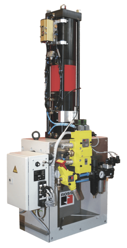
Pneumatic and hydraulic cylinder presses are some of the most common machines used in manufacturing. They are used to assemble or form products from wiring harnesses to metal parts and even press fit ROSS valve internal assemblies. They are simple machines consisting of a cylinder, a control valve, and a device used to actuate the valve. Cylinder presses are popular because they are simple yet can produce a lot of force, enabling a great deal of work with a small table-top machine reaching up to 13,000 lbf. However, this also makes them potentially hazardous machines that require a safety control system to prevent motion when an operator requires access to the point of operation.
Standards
Because these machines are very specific and hazardous there are standards for pneumatic and hydraulic cylinder presses. This means that the machine has specific minimum requirement that typically cannot be reduced or circumvented through the use of risk assessment and risk reduction methods. This is not to say that risk assessment and risk reduction is not needed as they will be required when the machine is integrated into a more complete system.
The specific C Type standards are:
- ANSI B11.2:2013 Safety Requirements for Hydraulic & Pneumatic Power Presses
- When a single failure occurs in fluid power circuits that control hazardous motion, the safety function shall (1) prevent initiation of hazardous motion and (2) initiate a stop command and prevent re-initiation, or prevent re-initiation at the next stop command.
- CSA Z142:10 Code for power press operation: Health, safety, and safeguarding requirements
- Hydraulic/pneumatic circuits used for press cycle initiation and controls that affect operator safety at the point of operation shall meet the requirements that (a) a single fault in any part does not lead to loss of the safety function, (b) a single fault is detected at the time of failure. If such detection is not practicable, the fault shall be detected at the next demand upon the safety function, (c) when a single fault occurs, the safety function is always performed, and a safe state is maintained until the fault is corrected, and (d) all reasonably foreseeable faults are detected.
- ISO 16092-4:2017 Machine Tool Safety – Presses – Part 4: Safety requirements for pneumatic presses
-
The standard suggests gravity-related issues such as prevention of unintended gravity fall during production (down-stroking press). There must be a restraint device that consists of one or more of the following measures, provided that they are capable of holding up the slide/ram: return spring, clamping device, two pneumatic restraint valves, one of which is fitted as close as possible to the cylinder outlet, using flanged or welded pipework, capable of holding the slide/ram.
-
- ISO 16092-3:2017 Machine tools safety – Presses – Part 3: Safety requirements for hydraulic presses

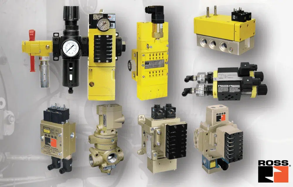
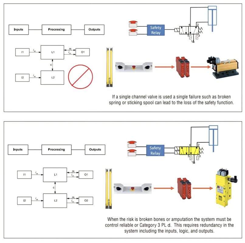
Knowing that we need a control reliable or Category 3, PL d system, the control reliability must include the inputs, logic, and outputs. Using a single channel valve can result in the loss of the safety function through the failure of single component such as solenoid, spring, or internal component. Choosing the best safety rated system and output device will depend on the complete machine specifics and the risk assessment of that machine that utilizes the cylinder press.
Risk Assessment & Solution
Considerations during the risk assessment of a cylinder press application to determine the most appropriate solution should include:
- Force calculations
- The effect of gravity
- Stopping time and safe distance calculations
- Failure modes of the cylinder press and automation
The typical cylinder press will simply go down when actuated and return up when de-actuated. The primary risk is having a hand in the point of operation during the downstroke. This up and down function is accomplished with a 5/2 valve function in which port 2 is pressurized during de-energization and port 4 during energization. For a safety rated system this can be accomplished with a safety rated dual 5/2 Category 4, PL e valve.
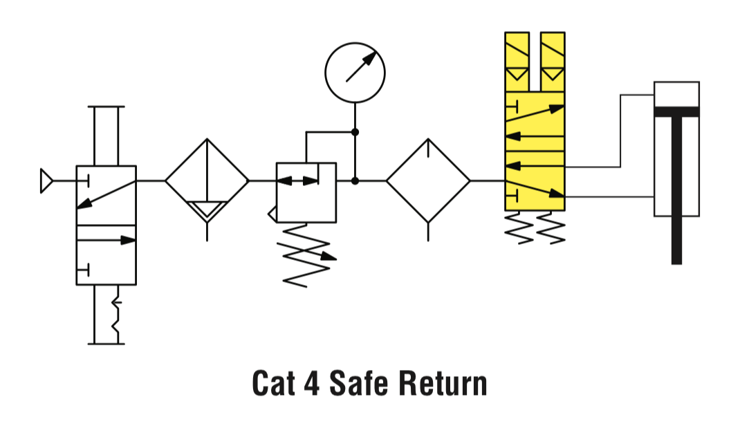
The most basic safety control system will simply require two safe outputs to control the valve’s main solenoids if using an internally monitored valve. This may have some form of feedback should a fault occur that can be used to prevent the reset of the safety system. If the safety system has the capability of actively monitoring sensor feedback, then an externally monitored dual 5/2 valve can be utilized. The residual risks in this type of system are the motion of the return stroke which should not create any pinch points and the risk of gravity due to the loss of supply pressure. These can be mitigated with the use of a check valve on the supply or through mechanical means on the cylinder.
In some cases, reversing the cylinder can create potential hazards due to the work being done. A common risk is parts under load being ejected if the reversal occurs prior to the work being completed. The machine would typically use guarding to protect the operator but if an interlock is opened and power lost during the cycle the safest outcome could be the cylinder stopping. This stopping of a cylinder can be accomplished a few ways depending on the exact risk.
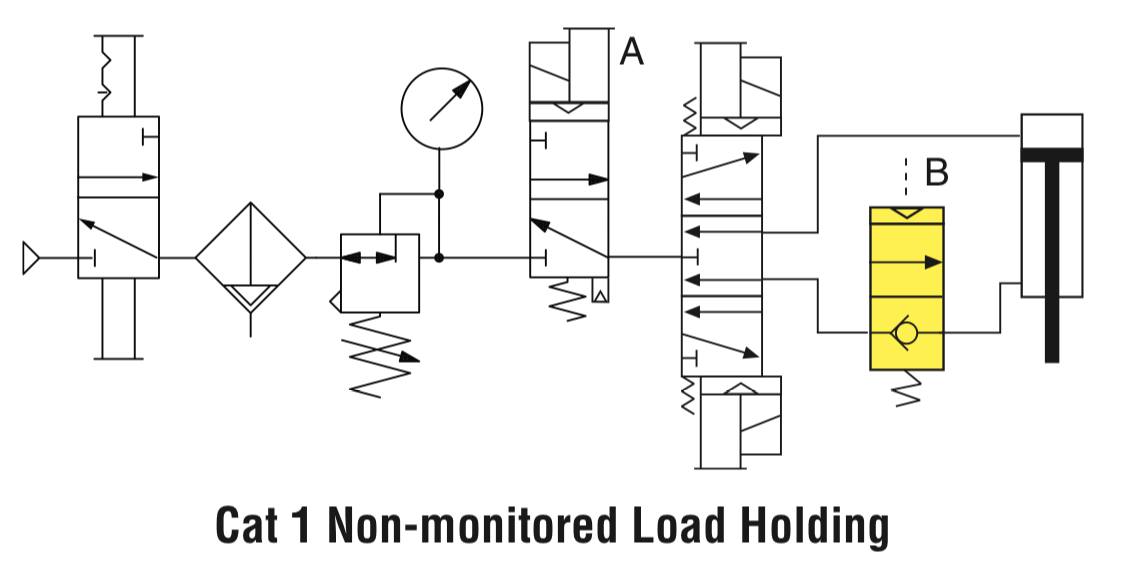
If the risk is largely due to gravity the most effective solution for stopping may be to have a safety rated exhaust valve supplying the standard Category 1 cylinder control valve and utilize a pilot operated check, mechanical device, or combination of the two. A key aspect of risk assessment is that it is iterative. You provide a solution that will leave residual risk which can then be addressed. In this case the main risk at the point of operation with full force on the cylinder. The safety rated exhaust valve eliminates that risk, but the residual risk is due to gravity which could be minimal requiring a simple Category 1 check valve.
If the gravity risk is substantial, then Category 3 pilot operated checks or safety rated mechanical catchers or brakes or a combination of those for diversity and redundancy.
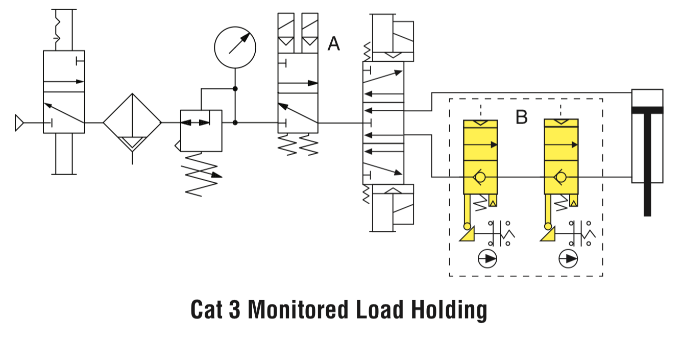
Monitoring of those devices is crucial in obtaining the needed diagnostic coverage to meet the requirements for a Performance Level d system. Simple redundancy and or diversity will not meet the requirements. Frequently monitoring of the machine function is referenced as the diagnostic coverage. The end positions of the cylinder stroke will provide feedback showing that the cylinder is functioning correctly. This is actually monitoring the single channel control valve and not the safety function which is designed to stop the machine in mid-stroke. It is advisable that this function be periodically tested.
Additionally, it should be noted that many mechanical devices used on cylinders are designed to hold a stopped cylinder, not stop a moving cylinder. These often will contain a disclaimer stating it is not intended as a safety device. There are devices available that are certified for use in presses.
If the risk is not only gravity but a machine that must remain in compression during the work function such as assembling a spring loaded type of device, pressure will need to be trapped on both ends of the cylinder and there must be a method to safety relieve this pressure if necessary. A safety rated 5/3 closed center valve can be used for Category 3 or 4 PL d or e applications. This valve will use dual internals to redundantly control the supply to each end of the cylinder and dual internals to redundantly control the air exhausting out of the end of each cylinder. Similar to a safe return valve, this valve handled the control function in a safety rated manner. This is only available with position sensors for external monitoring and therefore requires a programmable safety controller to perform the safe monitoring function.

Summary
There are many factors to consider when assessing/designing and implementing cylinder press solutions that include press force, stopping times and the effects of gravity. There are also several standards that apply so users need to know where the machine is going and how it is going to be used in order to select the correct safety solution. ROSS Controls can help guide users through the selection and design process to help users implement effective solutions that meet the requirements of the standards.
Reference: ROSS Controls
สำหรับข้อมูลเพิ่มเติม โปรดติดต่อเรา:
โทร: 02-384-6060 | ไลน์: @flutech.co.th | อีเมล: sales@flutech.co.th | เฟสบุ๊ค: @flutech.co.th | เว็บไซต์: https://flutech.co.th