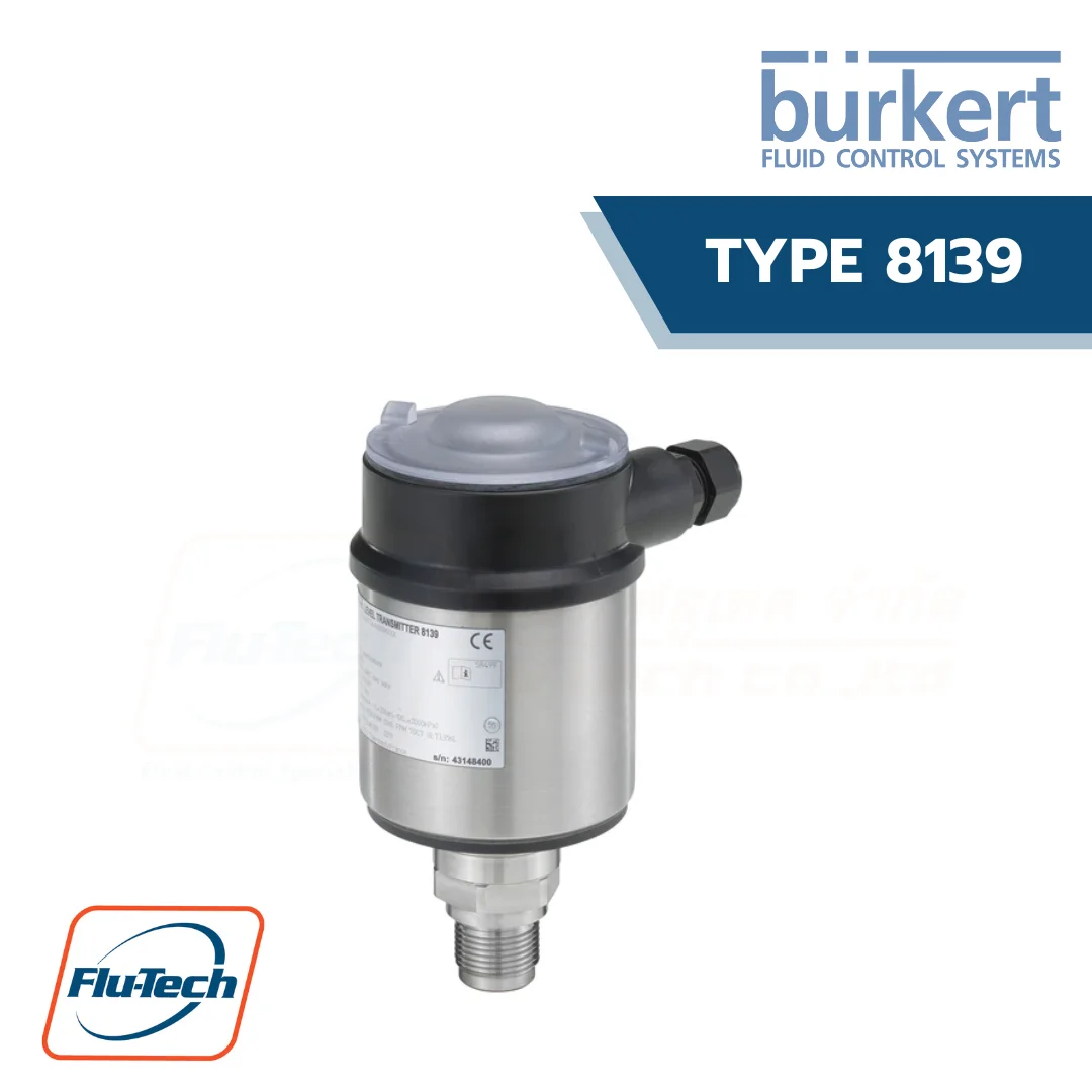
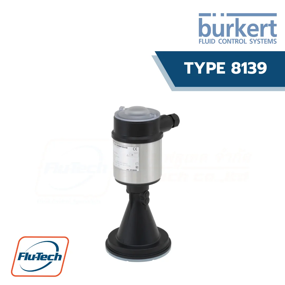
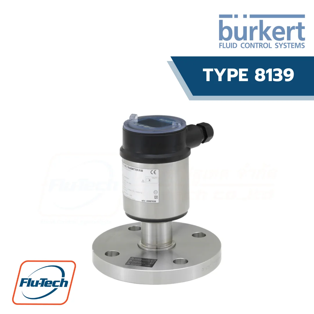
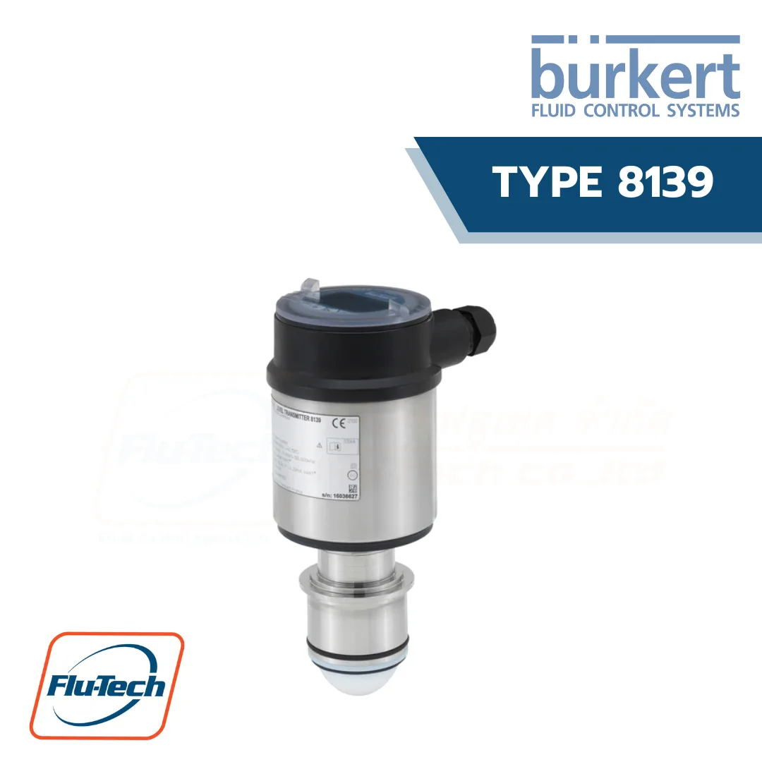
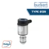
Radar level meter for liquids suitable for use in applications with aggressive fluids as well as with hygienic requirements
The Type 8139 is a non-contact radar level measuring device for continuous level measurement.
DOWNLOAD CATALOG (ดาวน์โหลดแคตตาล็อก)
BURKERT TYPE 8139 สามารถใช้ได้ร่วมกับ
General Technical Data
Product properties |
|
| Non wetted parts | Depending on antenna system. Detailed information can be found in chapter “2. Product versions” on page 5. |
| Materials | Please make sure the device materials are compatible with the fluid you are using. Detailed information can be found in chapter “4.1. Chemical Resistance Chart – Bürkert resistApp” on page 7. |
| Housing | Plastic PBT (Polyester), PPS and stainless steel 316L (1.4404) |
| Cover | PC transparent |
| Seal between housing and housing cover | EPDM |
| Cable gland | PA |
| Blind plug | PA |
| Ground terminal | Stainless steel 316L |
| Wetted parts | Depending on antenna system. Detailed information can be found in chapter “2. Product versions” on page 5. |
| Dimensions | Detailed information can be found in chapter “5. Dimensions” on page 8. |
| Weights | Approx. 2…17.2 kg (depending on process connection and antenna) |
| Measuring variable | Distance between the end of the sensor antenna and the product surface. |
| Measuring range | Max. 30 m (depending on antenna system). Detailed information can be found in chapter “2. Product versions” on page 5. |
| Beam angle1.) | Depending on antenna system. Detailed information can be found in chapter “2. Product versions” on page 5. |
| Damping (63 % of the input variable) | 0…999 s, adjustable |
| Step response time2.)3.) | ≤ 3 s |
| Product accessories Display | LCD in full dot matrix (optional, must be ordered separately) |
Performance data |
|
| Blocking distance | Null |
| Measurement deviation | According to EN 60770-1: ≤ 1 mm for liquids (measuring distance > 0.25 m). Detailed infor-mation can be found in chapter “6.1. Measurement deviation diagram” on page 11. |
| Measuring range resolution | 1 mm |
| Measuring frequency | W-Band (80 GHz technology) |
| Measuring cycle time2.) | Approx. 700 ms |
| Temperature drift | < 0.03 %/10K relating to the 16 mA span or max. 0.3 % |
| Repeatability4.) | ≤ 1 mm |
| Vibration resistance | Depending on antenna system. Detailed information can be found in chapter “2. Product versions” on page 5. |
| Shock resistance | 100 g, 6 ms according to EN 60068-2-27 (mechanical shock) |
Electrical data |
|
| Operating voltage (Un) | Actual valve output: 4…20 mA Max. load (current output): < 500 Ω |
| Starting current | 1 pulse per m3 |
| Load resistor | RS 485 interface, Modbus-RTU |
| Output signal | 18…36 V DC, 5 W |
| Signal resolution | 0.3 µA |
| Range of the output signal | 3.8…20.5 mA/HART (default setting) |
| Fault signal | Current output: mA value unchanged, 20.5 mA, 22 mA or < 3.6 mA (adjustable) |
| Max. output current | 22 mA |
| Residual ripple (at DC) | For 12 V< Un < 18 V: ≤ 0.7 Veff (16…400 Hz) For 18 V< Un < 35 V: ≤ 1.0 Veff (16…400 Hz) |
| Voltage supply cable | • Cable diameter: 5…9 mm • Wire cross-section (spring-loaded terminals): – massive wire, stranded wire: 0.2…2.5 mm2 (AWG 24…14) – stranded wire with end sleeve: 0.2…1.5 mm2 (AWG 24…16) |
Media data |
|
| Process temperature | Depending on antenna system. Detailed information can be found in chapter “2. Product versions” on page 5. |
| Process pressure | Depending on antenna system. Detailed information can be found in chapter “2. Product versions” on page 5. |
Process/Port connection & communication |
|
| Process connection | • Mounting bracket 170 mm (supplied as standard) or 300 mm (accessory) (version with plastic horn antenna) • Thread G or NPT – ¾” or 1½” (version with integrated horn antenna) • Flange DN50, DN100 DIN 2501 (version with encapsulated antenna system) • Clamp 2″ DIN 32676, ISO 2852 (hygiene connection version with encapsulated anten-na system) |
| Electrical connection | Cable gland M20 x 1.5 |
Approvals and Certificates |
|
| Standards Degree of protection according to IEC/EN 60529 |
IP66/IP67 with cable plug mounted and tightened M20 x 1.5 |
| Overvoltage category according to IEC 61010-1 | Category III |
| Protection class according to IEC 61010-1 |
Class III |
| Directives | |
| CE directives | The applied standards, which verify conformity with the EU Directives, can be found on the EU Type Examination Certificate and/or the EU Declaration of conformity (if applicable) |
| NAMUR recommendations | NE21- Electromagnetic compatibility of equipment NE43 – Signal level for fault information from measuring transducers NE53 – Compatibility of field devices and display/adjustment components NE107 – Self-monitoring and diagnosis of field devices |
| Approvals | |
| ATEX/IECEx | EN IEC 60079-0, EN 60079-11, EN 60079-26 Detailed information can be found in chapter “3.1. ATEX/IECEx-Certification” on page 7. |
Environment and installation |
|
| Ambient temperature | Operation and storage: – 40…+ 80 °C (- 40…+ 176 °F) |
| Temperature derating | Depending on antenna system. Detailed information can be found in chapter “6.2. Tem-perature derating diagram” on page 12. |
| Relative air humidity | 20…85 %, without condensation |
| Height above sea level | By default: max. 2000 m With connected overvoltage protection: max. 5000 m |
| Pollution degree | Degree 4 (when used with fulfilled housing protection) |
*For selecting thecorrect product please refer to the technical data, images and notes for proper use according to the data sheet, or contact Flu-Tech directly.
สอบถามข้อมูลเพิ่มเติม ติดต่อเรา :
02-384-6060 (อัตโนมัติ) [email protected] บริษัท ฟลูเทค จำกัด Flu-tech @flutech.co.th
