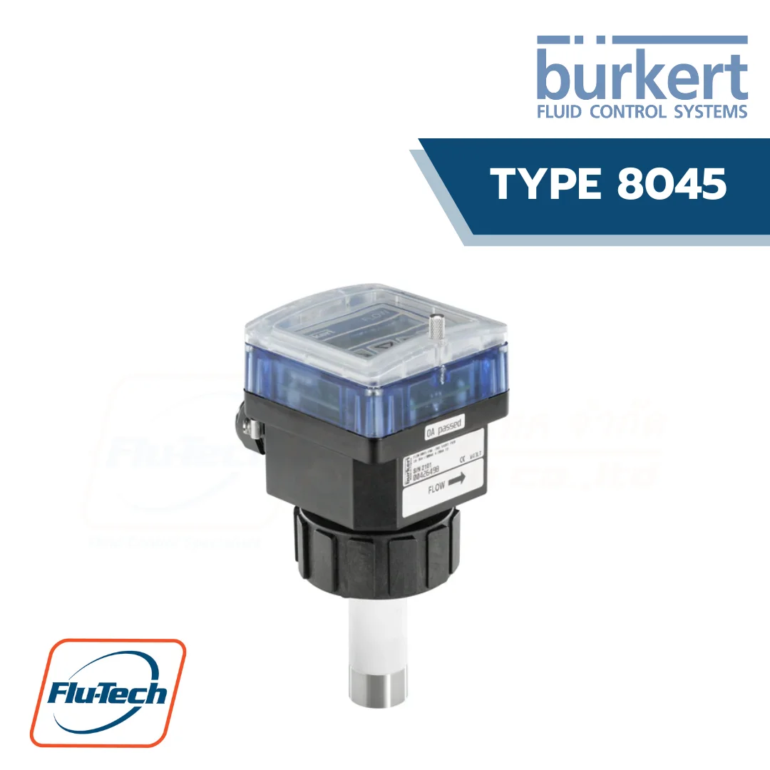
Insertion magnetic inductive flowmeter
The electromagnetic flowmeter 8045 is made up of an electronic module including a backlit display, operating keys and a sensor consisting of PVDF or stainless steel material. It has been designed to measure a flow rate of neutral and slightly aggressive fluids with a conductivity of more than 20 µS/cm in DN 06…DN 400 pipes.
It is equipped with a 4…20 mA output, a digital output (pulse output by default). Some versions are equipped with two relay outputs and one digital input. Two independent totalizers allow counting the flow rate.
This flowmeter is available either with a G 2″ connection with a PVDF sensor or, a G 2″ or clamp connection with a stainless steel sensor which are designed for use with Type S020 Insertion fitting.
The version with a stainless steel sensor can be used in applications with higher pressures (PN 16) and higher temperatures (110 °C). The version with Alloy C22 electrodes has been designed for applications with aggressive fluids (chemicals) and especially sea water applications.
DOWNLOAD CATALOG (ดาวน์โหลดแคตตาล็อก)
BURKERT TYPE 8045 สามารถใช้ได้ร่วมกับ
-
 BURKERT - TYPE 2030 Pneumatically operated 2/2 way diaphragm valve CLASSIC with plastic valve body
-
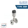 BURKERT - TYPE 2301 Pneumatically operated 2 way Globe Control Valve
-
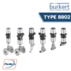 Burkert - Type 8802 - Continuous control Valve Systems Overview (Type ELEMENT)
-
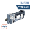 Burkert - Type 8644 AirLINE SP electropneumatic automation system
General Technical Data
Product properties |
|
| Housing, cover, nut | Stainless steel 304/1.4301 |
| Electrode | • Version with flow sensor in PVDF: PC (glass fibre reinforced for housing) • Version with flow sensor in stainless steel: back PPA (glass fibre reinforced) |
| Lid | • Version with flow sensor in PVDF: PC • Version with flow sensor in stainless steel: PSU |
| Seal | NBR |
| Seal | Silicone |
| Front panel foil | Polyester |
| Holder | Stainless steel 1.4404/316L (for flowmeter with clamp process connection, over the clamp) |
| Screws | Stainless steel |
| Cable glands | PA with neoprene seal |
| Mounting ring | Polysulphone, glass fibre reinforced |
| Clamp | Stainless steel 1.4404/316L |
| Electrodes | • Stainless steel 1.4404/316L • Alloy C22 |
| Sensor holder | • PVDF • Stainless steel 1.4404/316L |
| Earth ring | Only with version with flow sensor in PVDF: • Stainless steel 1.4404/316L • Alloy C22 |
| Electrode holder | Only with version with flow sensor in stainless steel: PEEK (conform to FDA) |
| Dimensions | Detailed information can be found in chapter “4. Dimensions” on page 8. |
| Surface quality | For clamp process connection: Ra < 0.8 µm |
| Measuring principle | Electromagnetic |
| Sensor element | Electrodes |
| Compatibility | • For flowmeter with G 2″ process connection: Any pipe from DN 06…DN 400 which is fitted with Bürkert S020 Insertion fitting with G 2″ sensor connection. • For flowmeter with clamp process connection: Any pipe from DN 32…DN 100 which is fitted with Bürkert S020 Insertion fitting with clamp sensor connection. |
| Pipe diameter | • For flowmeter with G 2″ process connection: DN 06…DN 400 • For flowmeter with clamp process connection: DN 32…DN 100 |
| Measuring range | • Flow rate: 0.4…75000 l/min • Flow velocity: 0.2…10 m/s |
Performance data |
|
| Measurement deviation | • Teach-In: ± 0.5 % of the measured value1.) at Teach-In flow rate value • Standard K-factor: ± 3.5 % of the measured value1.) |
| Repeatability | ± 0.25 % of the measured value1.) |
| Linearity | ± 0.5 % of full scale1.) |
| 4…20 mA output uncertainty | ± 1 % of range |
Electrical data |
|
| Operating voltage | 18…36 V DC ± 0.5 %, filtered and regulated (3 wires) |
| Power source (not supplied) | Limited power source according to UL/EN 60950-1 standards or limited energy circuit according to UL/EN 61010-1 §9.4 |
| DC reverse polarity protection | Yes |
| Current consumption | ≤ 300 mA (at 18 V DC) |
| Input (DI1) | • Supply voltage: 18…36 V DC • Input impedance: 15 kΩ • min. pulse duration: 200 ms • Galvanic insulation, protected against polarity reversals of DC and voltage spikes |
| Outputs | • Current (analogue output AO1): – 4…20 mA – Sink or source (by wiring) – 22 mA to indicate a fault – Max. loop impedance: 1300 Ω at 36 V DC; 1000 Ω at 30 V DC; 700 Ω at 24 V DC; 450 Ω at 18 V DC • Transistor (digital output DO1): – Type: NPN or PNP (wiring dependent), open collector – Function: pulse output (by default), user configurable – 0…250 Hz, 5…36 V DC, 100 mA max. – Duty cycle (pulse duration/period) if frequency > 2 Hz: ½ – Min. pulse duration if frequency < 2 Hz: 250 ms – Galvanic insulation, protected against polarity reversals of DC and short-circuits • Relay (digital outputs DO2 and DO3): – 2 normally open, freely adjustable (hysteresis by default) – Non UL recognized device: 250 V AC/3 A or 40 V DC/2 A (resistive load) – UL recognized device: 30 V AC/42 Vpeak/2 A or 60 V DC/1 A – Max. cutting power of 750 VA (resistive load) – Life span of min. 100000 cycles |
| Voltage supply cable | • Shielded • External diameter (cable): 6…12 mm (1 cable per cable gland) or 4…5 mm when using a mul-ti-way seal (2 cables per cable gland) • Cross section of wires: 0.5…1.5 mm2 |
Medium data |
|
| Fluid temperature | • Version with flow sensor in PVDF: 0…+ 80 °C (+ 32…+ 176 °F) (depends on fitting) • Version with flow sensor in stainless steel: – 15…+ 110 °C (+ 5…+ 232 °F) (depends on fitting) Detailed information can be found in chapter “5.1. Pressure temperature diagram” on page 11 and in the data sheet of the fitting, see data sheet Type S020 . |
| Fluid pressure | • Version with flow sensor in PVDF: max. PN 10 (145.1 PSI) • Version with flow sensor in stainless steel: – Max. PN 10 (145.1 PSI) (with plastic fitting) – Max. PN 16 (232.16 PSI) (with metal fitting) |
| Conductivity | Min. 20 µS/cm |
| Viscosity | < 1000 mPa.s |
Process/Port connection & communication |
|
| Process connection | • G 2″ for use with Type S020 Insertion fitting • Clamp for use with Type S020 Insertion fitting or any pipe equipped with our clamp sensor connection. |
| Electrical connection | 2 cable glands M20 × 1.5 |
Approvals and certificates |
|
| Degree of protection2.) accord-ing to IEC/EN 60529 | IP65 under the following conditions: device wired, cover screwed tight and cable glands mounted and tightened or with blind plug if not used |
| CE directives | The applied standards, which verify conformity with the EU Directives, can be found on the EU Type Examination Certificate and/or the EU Declaration of conformity (if applicable). |
| Pressure Equipment Directive | Complying with Article 4, Paragraph 1 of 2014/68/EU directive |
| Certificate | • FDA declaration of conformity (for stainless steel or PVDF sensor with FKM or EPDM seal) • ECR1935/2004 declaration (only for stainless steel sensor with EPDM seal) |
| Certification | UL-Recognized for US and Canada |
Environment and installation |
|
| Ambient temperature | • Operation: – 10…+ 60 °C (+ 14…+ 140 °F) • Storage: – 20…+ 60 °C (- 4…+ 140 °F) |
| Relative air humidity | ≤ 80 %, without condensation |
| Height above sea level | Max.2000 m |
| Operating condition | Continuous |
| Equipment mobility | Fixed device |
| Application range | Indoorandoutdoor(protectthedeviceagainstelectromagneticinterference,ultravioletrays andagainsttheeffectsofclimaticconditions) |
| Installation category | Category II according to UL/EN 61010-1 |
| Pollution degree | Degree 2 according to UL/EN 61010-1 |
*For selecting thecorrect product please refer to the technical data, images and notes for proper use according to the data sheet, or contact Flu-Tech directly.
สอบถามข้อมูลเพิ่มเติม ติดต่อเรา :
02-384-6060 (อัตโนมัติ) [email protected] บริษัท ฟลูเทค จำกัด Flu-tech @flutech.co.th