
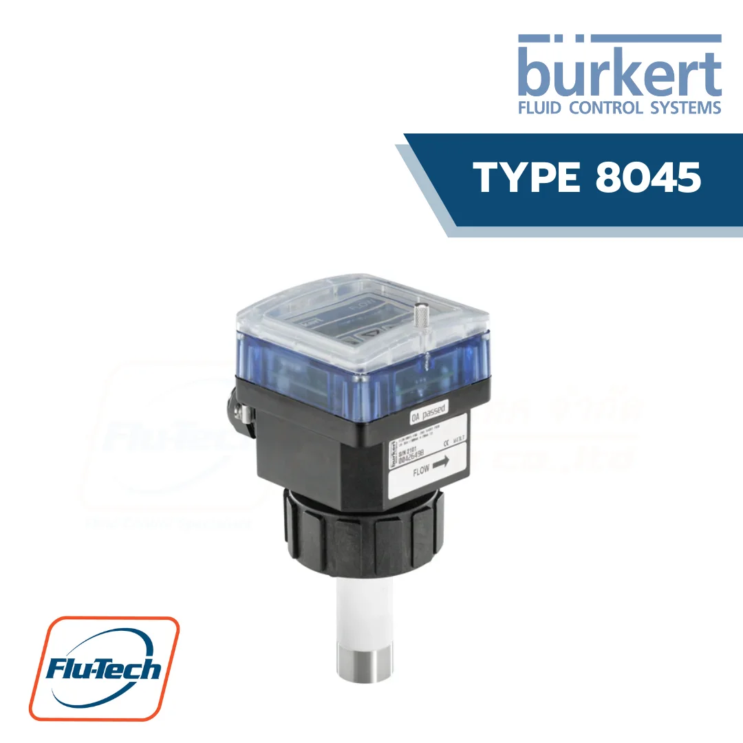
Type 8045 – Electromagnetic insertion flowmeter
The electromagnetic flowmeter Type 8045 consists of an electronic module with backlit display, operating buttons and a sensor made from PVDF or stainless steel. It is suitable for pipelines with a nominal diameter of between DN 06 and DN 400 and neutral or aggressive liquids with conductivity greater than 20 μS/cm. Type 8045 is fitted with a 4 mA to 20 mA current output and a digital output (preset as a pulse output). Some variants have 2 relay outputs and one digital input. Two independent totalisers allow the volume flow to be metered. This flowmeter is available with either a G2” connection for a PVDF sensor or a G2” or clamp connection for a stainless steel sensor, both of which are designed for use with a Type S020 insertion fitting. The variant with stainless steel sensor is for applications with higher pressures (PN 16) and higher temperatures (110°C). The variant with electrodes made of alloy C22 is suitable for applications with aggressive liquids (chemicals) and particularly for seawater applications.
DOWNLOAD DATA SHEETS
Can be combined with
-
 BURKERT - TYPE 2030 Pneumatically operated 2/2 way diaphragm valve CLASSIC with plastic valve body
-
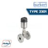 BURKERT - TYPE 2301 Pneumatically operated 2 way Globe Control Valve
-
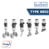 Burkert - Type 8802 - Continuous control Valve Systems Overview (Type ELEMENT)
-
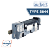 Burkert - Type 8644 AirLINE SP electropneumatic automation system
General Technical Data
Product properties |
|
| Housing, cover, nut | Stainless steel 304/1.4301 |
| Electrode | • Version with flow sensor in PVDF: PC (glass fibre reinforced for housing) • Version with flow sensor in stainless steel: back PPA (glass fibre reinforced) |
| Lid | • Version with flow sensor in PVDF: PC • Version with flow sensor in stainless steel: PSU |
| Seal | NBR |
| Seal | Silicone |
| Front panel foil | Polyester |
| Holder | Stainless steel 1.4404/316L (for flowmeter with clamp process connection, over the clamp) |
| Screws | Stainless steel |
| Cable glands | PA with neoprene seal |
| Mounting ring | Polysulphone, glass fibre reinforced |
| Clamp | Stainless steel 1.4404/316L |
| Electrodes | • Stainless steel 1.4404/316L • Alloy C22 |
| Sensor holder | • PVDF • Stainless steel 1.4404/316L |
| Earth ring | Only with version with flow sensor in PVDF: • Stainless steel 1.4404/316L • Alloy C22 |
| Electrode holder | Only with version with flow sensor in stainless steel: PEEK (conform to FDA) |
| Dimensions | Detailed information can be found in chapter “4. Dimensions” on page 8. |
| Surface quality | For clamp process connection: Ra < 0.8 µm |
| Measuring principle | Electromagnetic |
| Sensor element | Electrodes |
| Compatibility | • For flowmeter with G 2″ process connection: Any pipe from DN 06…DN 400 which is fitted with Bürkert S020 Insertion fitting with G 2″ sensor connection. • For flowmeter with clamp process connection: Any pipe from DN 32…DN 100 which is fitted with Bürkert S020 Insertion fitting with clamp sensor connection. |
| Pipe diameter | • For flowmeter with G 2″ process connection: DN 06…DN 400 • For flowmeter with clamp process connection: DN 32…DN 100 |
| Measuring range | • Flow rate: 0.4…75000 l/min • Flow velocity: 0.2…10 m/s |
Performance data |
|
| Measurement deviation | • Teach-In: ± 0.5 % of the measured value1.) at Teach-In flow rate value • Standard K-factor: ± 3.5 % of the measured value1.) |
| Repeatability | ± 0.25 % of the measured value1.) |
| Linearity | ± 0.5 % of full scale1.) |
| 4…20 mA output uncertainty | ± 1 % of range |
Electrical data |
|
| Operating voltage | 18…36 V DC ± 0.5 %, filtered and regulated (3 wires) |
| Power source (not supplied) | Limited power source according to UL/EN 60950-1 standards or limited energy circuit according to UL/EN 61010-1 §9.4 |
| DC reverse polarity protection | Yes |
| Current consumption | ≤ 300 mA (at 18 V DC) |
| Input (DI1) | • Supply voltage: 18…36 V DC • Input impedance: 15 kΩ • min. pulse duration: 200 ms • Galvanic insulation, protected against polarity reversals of DC and voltage spikes |
| Outputs | • Current (analogue output AO1): – 4…20 mA – Sink or source (by wiring) – 22 mA to indicate a fault – Max. loop impedance: 1300 Ω at 36 V DC; 1000 Ω at 30 V DC; 700 Ω at 24 V DC; 450 Ω at 18 V DC • Transistor (digital output DO1): – Type: NPN or PNP (wiring dependent), open collector – Function: pulse output (by default), user configurable – 0…250 Hz, 5…36 V DC, 100 mA max. – Duty cycle (pulse duration/period) if frequency > 2 Hz: ½ – Min. pulse duration if frequency < 2 Hz: 250 ms – Galvanic insulation, protected against polarity reversals of DC and short-circuits • Relay (digital outputs DO2 and DO3): – 2 normally open, freely adjustable (hysteresis by default) – Non UL recognized device: 250 V AC/3 A or 40 V DC/2 A (resistive load) – UL recognized device: 30 V AC/42 Vpeak/2 A or 60 V DC/1 A – Max. cutting power of 750 VA (resistive load) – Life span of min. 100000 cycles |
| Voltage supply cable | • Shielded • External diameter (cable): 6…12 mm (1 cable per cable gland) or 4…5 mm when using a mul-ti-way seal (2 cables per cable gland) • Cross section of wires: 0.5…1.5 mm2 |
Medium data |
|
| Fluid temperature | • Version with flow sensor in PVDF: 0…+ 80 °C (+ 32…+ 176 °F) (depends on fitting) • Version with flow sensor in stainless steel: – 15…+ 110 °C (+ 5…+ 232 °F) (depends on fitting) Detailed information can be found in chapter “5.1. Pressure temperature diagram” on page 11 and in the data sheet of the fitting, see data sheet Type S020 . |
| Fluid pressure | • Version with flow sensor in PVDF: max. PN 10 (145.1 PSI) • Version with flow sensor in stainless steel: – Max. PN 10 (145.1 PSI) (with plastic fitting) – Max. PN 16 (232.16 PSI) (with metal fitting) |
| Conductivity | Min. 20 µS/cm |
| Viscosity | < 1000 mPa.s |
Process/Port connection & communication |
|
| Process connection | • G 2″ for use with Type S020 Insertion fitting • Clamp for use with Type S020 Insertion fitting or any pipe equipped with our clamp sensor connection. |
| Electrical connection | 2 cable glands M20 × 1.5 |
Approvals and certificates |
|
| Degree of protection2.) accord-ing to IEC/EN 60529 | IP65 under the following conditions: device wired, cover screwed tight and cable glands mounted and tightened or with blind plug if not used |
| CE directives | The applied standards, which verify conformity with the EU Directives, can be found on the EU Type Examination Certificate and/or the EU Declaration of conformity (if applicable). |
| Pressure Equipment Directive | Complying with Article 4, Paragraph 1 of 2014/68/EU directive |
| Certificate | • FDA declaration of conformity (for stainless steel or PVDF sensor with FKM or EPDM seal) • ECR1935/2004 declaration (only for stainless steel sensor with EPDM seal) |
| Certification | UL-Recognized for US and Canada |
Environment and installation |
|
| Ambient temperature | • Operation: – 10…+ 60 °C (+ 14…+ 140 °F) • Storage: – 20…+ 60 °C (- 4…+ 140 °F) |
| Relative air humidity | ≤ 80 %, without condensation |
| Height above sea level | Max.2000 m |
| Operating condition | Continuous |
| Equipment mobility | Fixed device |
| Application range | Indoorandoutdoor(protectthedeviceagainstelectromagneticinterference,ultravioletrays andagainsttheeffectsofclimaticconditions) |
| Installation category | Category II according to UL/EN 61010-1 |
| Pollution degree | Degree 2 according to UL/EN 61010-1 |
*For selecting thecorrect product please refer to the technical data, images and notes for proper use according to the data sheet, or contact Flu-Tech directly.
สอบถามข้อมูลเพิ่มเติม ติดต่อเรา :
02-384-6060 (อัตโนมัติ) [email protected] บริษัท ฟลูเทค จำกัด Flu-tech @flutech.co.th