Solenoid valves manifold Series 2500 OPTYMA-T
PNEUMAX – โมดูลเครือข่ายการควบคุม SERIES 2500 OPTYMA-T – SERIAL SYSTEMS General :
Using the 2540.03.25P output terminal it is possible to make any electrical signals not used by valves available on a 25 sub-D female connector at the right end of the manifold.
It is possible to then join a multi-core cable to link to the next manifold, or connect directly to one or two I/O modules.
The I/O modules can accept input or output signals, depending upon what is connected.
It is possible to connect the manifold to up to two I/O modules.
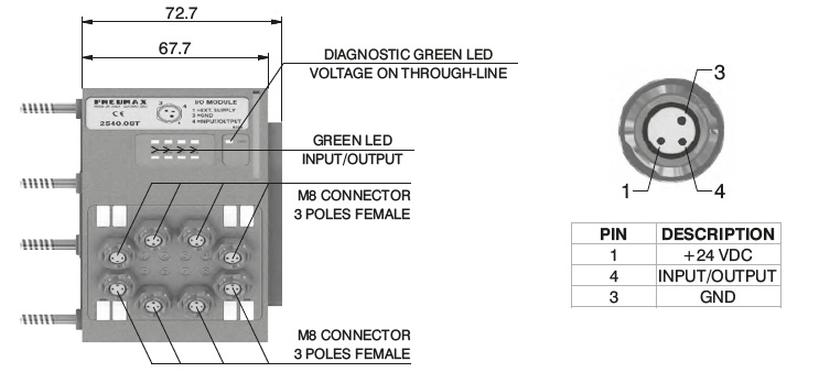
Each I/O module includes 8 diagnostic LEDs which indicate the presence of an Input / Output signal for each connector.
DOWNLOAD CATALOG (ดาวน์โหลดแคตตาล็อก)
Overall dimensions and I/O layout :
Input features:
Each connection can accept either two wire (switches, magnetic switches, pressure switches, etc.) or three wire connections (photocells, electronic end of stroke sensors, etc.) If +24VDC is required on at Pin 1 of each connector, it is possible to provide this via the through-line pin of the multi-pole connector.I.E :Pin 25 of the 25 pin multi-pole connector (code 2540.02.25P or 2540.12.25P)Pin 36-37 of the 37 pin multi-pole connector (code 2540.02.37P or 2540.12.37P)
Output features:
Attention: The output connections are not protected against short-circuit. Please pay attention when wiring (avoid Pin 4 being connected to Pin 3 or Pin 1).
สอบถามข้อมูลเพิ่มเติม ติดต่อเรา :
02-384-6060 (อัตโนมัติ) [email protected] บริษัท ฟลูเทค จำกัด Flu-tech @flutech.co.th

