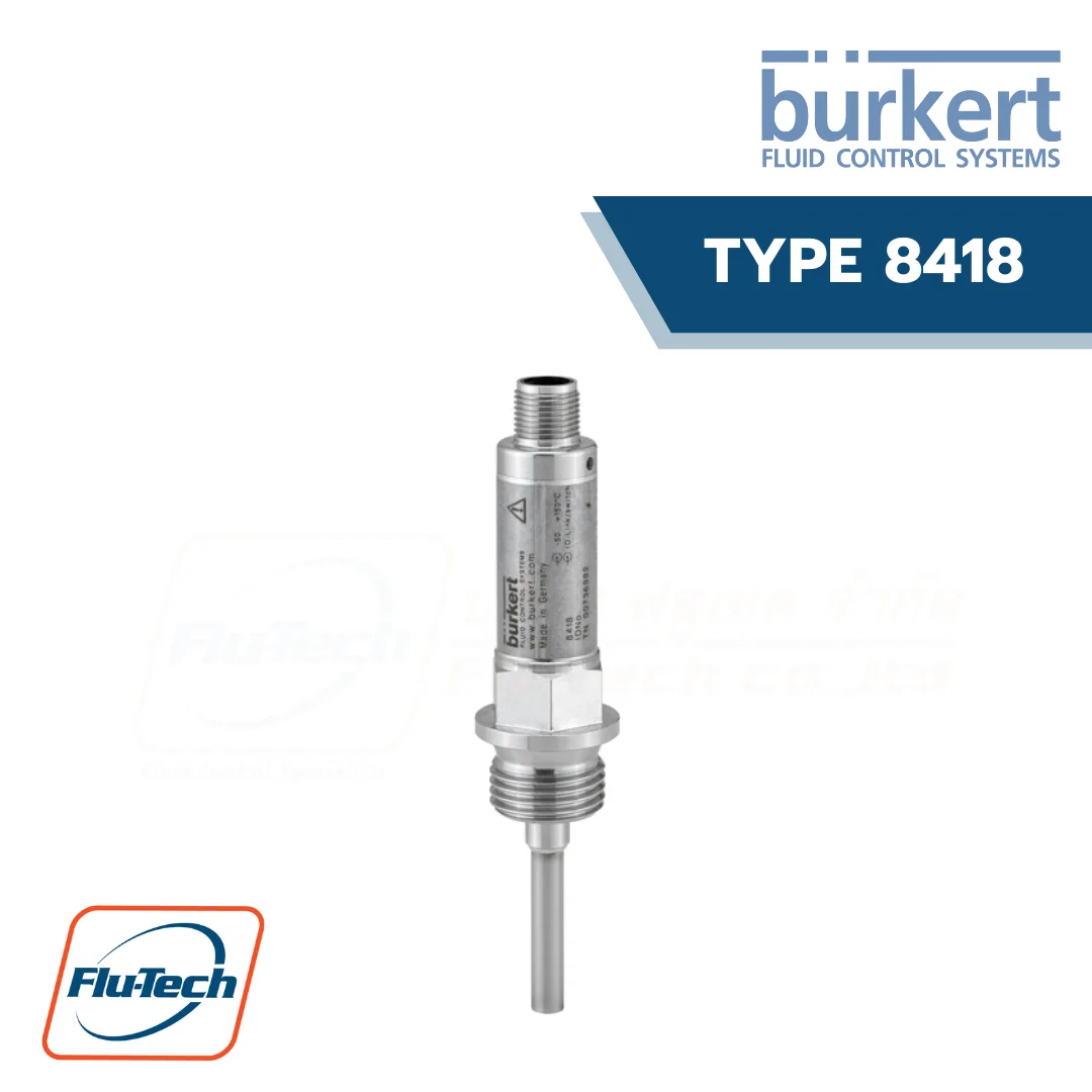
RTD Temperature sensor with IO-Link interface
The temperature sensor is used for temperature measurement and monitoring. The effect of the temperature on a resistance RTD temperature probe generates a signal, which is amplified, digitalized and processed.
DOWNLOAD CATALOG (ดาวน์โหลดแคตตาล็อก)
General Technical Data
Product Properties |
|
| Housing material (non-wetted parts) |
Stainless steel 1.4571 (316Ti)
|
| Process connection (wetted parts) | Stainless steel 1.4404 (316L) for thread connection version / Stainless steel 1.4435 (316L) for clamp connection version (with low delta ferrite content) |
| Protection tube (wetted parts) | Stainless steel 1.4404 (316L) for thread connection version / Stainless steel 1.4435 (316L) for clamp connection version |
|
Dimensions
|
Detailed information can be found in chapter “3. Dimensions” on page 6.
|
| Measurement element | RTD temperature probe Pt1000, four-wire circuit |
| Probe length | 50 or 100 mm |
| Measuring range |
– 50…+ 150 °C (- 58…+ 302 °F)
|
| Monitoring |
Measuring circuit: IO-Link event configurable and is available as device status
• Process data invalid • Measuring range overflow • Measuring range underflow • Device hardware fault |
|
Additional functions
|
• Fine adjustment • Change between °C/°F • Data format switchover (integer/floating point) • Switching outputs in SIO mode |
| Weight | Approx. 80 g for the version with thread connection and 100 mm probe length. The weight of the temperature sensor depends on the process connection and the inser- tion length. |
Performance Data |
|
|
Sampling rate
|
160 ms
|
| Transmission behaviour | Temperature linear |
| Response time | Protection tube Ø6 mm (standard): • t0.5 =5 s; t0.9 =12 s, in water with a flow velocity of 0.4 m/s • t0.5 =40 s; t0.9 =110 s, in air with a flow velocity of 3.0 m/s |
|
Measuring resolution
|
14 bit
|
| Measurement deviation | • Tolerance class A, ±(0.15+0.002×|t|1.)) °C according to EN 60751:2009/IEC 60751:2008 • ≤ ±(0.08 %)2.) (calibration of the electronic components) |
Electrical Data |
|
|
Operating voltage
|
• In IO-Link operation: 18…32 V DC, filtered and regulated • In switch operation: 9.6…32 V DC, filtered and regulated • Nominal voltage: 24 V DC |
| Power source (not supplied) | The auxiliary energy of the pressure sensor must meet SELV requirements; optionally, an energy-limited current circuit according to section 9.3 of DIN EN 61010-1 and UL 61010-1 can be used |
| Current consumption | • In idle operation: ≤ 12 mA (at nominal voltage) • In IO-Link operation: ≤ 20 mA (at nominal voltage) • In switch operation: ≤ 200 mA (at nominal voltage and with 2 digital outputs) |
|
DC reverse polarity protection
|
Yes
|
| Short circuit protection | Yes (clocked) |
| Current limiting | Yes |
| Switching current | ≤100 mA per output |
| Measuring current | ≤500 μA |
| Voltage drop at switching transistor | ≤ 2 V DC |
| Galvanic isolation | To the protection tube; no galvanic isolation between sensor and output |
|
Signal processing
|
Input filter: • digital filter, second order • filter time constant can be set |
|
Quantity output signal |
• 1 digital output in IO-Link operation • 2 digital outputs for switch operation (SIO mode; SIO = standard IO) |
| Switching functions configurable output signal | • Hysteresis function (Hysteresis configurable) or window function (hysteresis fixed setting, symetrical, ±0.25% of the measuring range) • Digital output PNP or NPN • Switch-on/switch-off delay (0…100 s) • NC or NO contact |
|
Cable
|
4-wire unshielded cable, max. 20 m
|
Medium Data |
|
|
Fluid
|
Liquid and gaseous medium
|
| Fluid pressure | • G 1⁄2″ process connection: Max. 40 bar • Clamp DN 10/20, according to DIN 3676. The permissible pressures are designed for an operating temperature range of – 10 to + 140 °C given use of suitable clamps and sealing materials. |
Process/Port Connection & Communication |
|
|
Process connection
|
• G 1⁄2″ according to EN 837 • Clamp DN 10/20 according to DIN 32676 Detailed information on the process connection can be found in chapter “4.3. Ordering chart” on page 7. |
| Electrical connection |
M12×1 male connector, 4 pin (A-coded, non rotating)
|
|
Digital communication: IO-Link – Communication interface
|
IO-Link device V1.1, downward compatible to V1.0
|
| Digital communication: IO-Link – Baud rate (data transfer rate) | COM 3 (230.4 kBaud) |
| Digital communication: IO-Link – Cycle time | Min. 2 ms |
| Digital communication: IO-Link – IO device description (IODD) | Depending on the ordered input range |
Approvals and Certificates |
|
|
Degree of protection
|
IP66/IP67/IP69 according to IEC/EN 60529, with connector screwed on
|
| Protection class | Class III according to EN 61140 |
|
CE directives
|
The applied standards, which verify conformity with the EU Directives, can be found on the EU Type Examination Certificate and/or the EU Declaration of conformity (if applicable). |
| Electromagnetic compatibility (EMC) | CE conformity according to EN 61326-2-3 • Interference emission: class B • Immunity to interference: to industrial requirements |
| Pressure equipment directives | The device does not meet the requirements for “safety accessories” within the meaning of the Pressure Equipment Directive 2014/68/EU. • Complying with Article 4, Paragraph 1 of 2014/68/EU directive Detailed information on the pressure equipment directive can be found in chapter “2.1. Pressure Equipment Directive” on page 5. |
Environment and Installation |
|
|
Ambient temperature
|
40…+85°C (-40…+185°F)(operation and storage)
|
| Temperature influence |
≤±0.0025% per K
|
| Relative air humidity | • During operation: ≤ 100 %, without condensation on the outer housing surface of the device • During storage: ≤ 90 %, without condensation |
| Climate class |
3K7 according to EN 60721-3-3
|
| Area of use |
Indoors and outdoors (protect this device against electromagnetic interference, ultravio- let rays and the effects of climatic conditions)
|
| Vibration resistance | According to EN 60068-2-6: 10 g with 10…500 Hz |
|
Shock resistance
|
According to EN 60068-2-27: • 20 g, 11 ms • 50 g, 1 ms |
|
Mounting position
|
Unrestricted
|
*For selecting thecorrect product please refer to the technical data, images and notes for proper use according to the data sheet, or contact Flu-Tech directly.
สอบถามข้อมูลเพิ่มเติม ติดต่อเรา :
02-384-6060 (อัตโนมัติ) [email protected] บริษัท ฟลูเทค จำกัด Flu-tech @flutech.co.th
