Inductive conductivity meter, ELEMENT Design
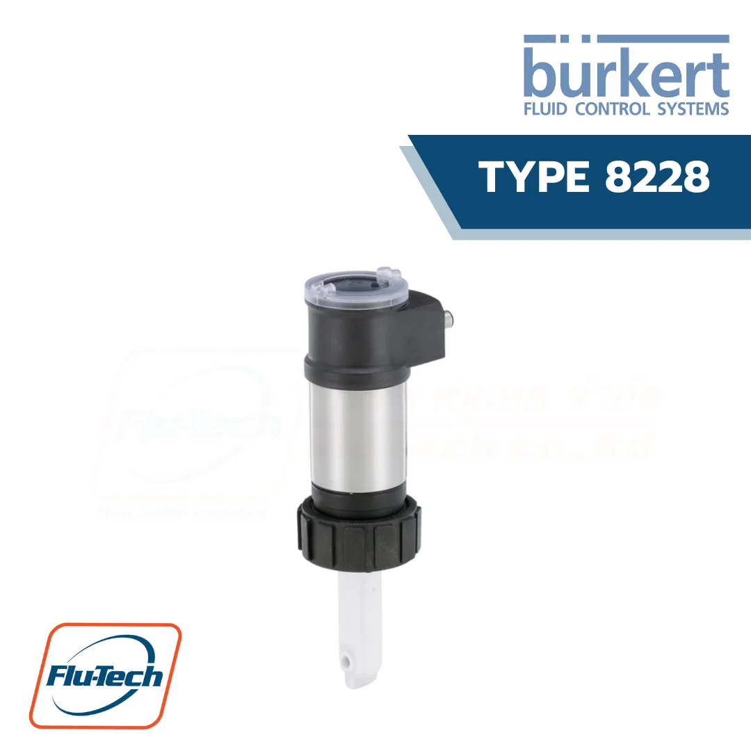
The Bürkert inductive Type 8228 conductivity meter is used in many industrial processes where measurements are required in aggressive or concentrated media such as acids, alkalis or liquids with high salt contents and a wide measuring range. Applications like cooling water monitoring (i.e. dilution control), industrial water treatment or the preparation and identification of cleaning liquids, for example in CIP processes. The device is available in two variants:
- The first is the standard variant with a G 2″ process connection to be mount in Type S020 fitting
- The second is the CIP variant with a 2″ clamp process connection according to ASME BPE (1.5″ clamp on request).
Downloads
Data Sheet User ManualBURKERT TYPE 8228 สามารถใช้ได้ร่วมกับ
General Technical Data
Product properties |
|
| Material | Please make sure the device materials are compatible with the fluid you are using. Detailed information can be found in chapter “4.1. Chemical Resistance Chart – Bürkert resistApp” on page 8. |
| Housing | Stainless steel 316L, PPS |
| Cover | Polycarbonate (PC), transparent (opaque on request) |
| Display/configuration module | PC |
| Navigation Key | PBT |
| Seal | EPDM, silicone |
| Screws | Stainless steel 1.4401 (316 (A4)) |
| Grounding terminal and screw | Stainless steel 1.4301 (304 (A2)) |
| Fixed connector holder | PPS CF30 |
| Others | Depending on the device version. Detailed information can be found in chapter “2. Product versions” on page 6 and in chapter “4.2. Material specifications” on page 8. |
| Wetted parts Depending on the device version. |
12 months nominal, depending on the water quality |
| Dimensions | Detailed information can be found in chapter “5. Dimensions” on page 9. |
| Compatibility | Depending on the device version. Detailed information can be found in chapter “2. Product versions” on page 6. |
| Pipe diameter | Depending on the device version. Detailed information can be found in chapter “2. Product versions” on page 6. |
| Temperature sensor | Integrated in the sensor |
| Temperature compensation | • None or • According to a predefined graph (NaCl, NaOH, HNO3 or H2SO4) or • According to a graph defined especially for your process |
| Concentration | Conversion of conductivity to dissolved electrolyte concentration (Total dissolved solids (TDS)) by using a user adjustable factor. |
Performance data |
|
| Measuring range resolution | 0.1 μS/cm |
| Measurement deviation | ± (2 % of the measured value + 5 μS/cm) |
| Linearity | ± 2 % |
| Repeatability | ± (0.2 % of the measured value + 2 μS/cm) |
| Response time t90 | From 3 s (without filter) to 40 s (with slow filter) |
| Temperature measurement | 0…+ 50 °C (+ 32…+ 122 °F) |
Electrical data |
|
| Operating voltage | 12…36 V DC, ± 10 % oscillation rate, filtered and regulated, Connection to main supply: permanent (through external SELV (Safety Extra Low Volt-age) and LPS (Limited Power Source) power supply) |
| Power source (not supplied) | Limited power source according to UL/EN 60950-1 standards or limited energy circuit according to UL/EN 61010-1 §9.4 |
| Protection against DC polarity reversal | Yes |
| Power / Current consumption | • Without the consumption of the current outputs and the transistor outputs: max. 1 W (25 mA at 12 V DC; inrush current ~100 mA) • With the consumption of the current outputs and the transistor outputs: max. 40 W (max. 1 A for the transistor outputs) |
| Output signal | • Pulse (transistor): – Polarized – Configurable through wiring and through parameterizing as sourcing (PNP) or sinking (NPN) – NPN-output: 1…36 V DC, max. 700 mA (or 500 mA max. per transistor if both transistor outputs are wired) – PNP-output: V+ supply voltage, max. 700 mA (or 500 mA max. per transistor if both transistor outputs are wired) – Galvanic insulation and protected against overvoltage, polarity reversals and short circuit • Current (3-wire): – 4…20 mA configurable through wiring and through parameterizing as sourcing or sinking, – 22 mA to indicate a fault (can be parametered) – Loop impedance max.: 1100 Ω at 36 V DC; 610 Ω at 24 V DC; 100 Ω at 12 V DC – Response time (10…90 %): 150 ms (default value) |
Medium data |
|
| Temperature | • PP: 0…+ 80 °C (+ 32…+ 176 °F) • PVDF: – 15…+ 100 °C (+ 5…+ 212 °F) • PEEK:- 15…+ 130 °C (+ 5…+ 266 °F) For the standard version, temperature limits may depend on the material the S020 fitting used is made of. Refer to the relevant instruction manual and data sheet and detailed information can be found in chapter “6.1. Pressure temperature diagram” on page 11. If the temperature ranges given for the device and the fitting are different, use the most restrictive range. |
| Pressure | • PP: max. PN6 (87 PSI) • PVDF: max. PN6 (87 PSI) • PEEK: max. PN10 (145 PSI) For the standard version, pressure limits may depend on the material the S020 fitting used is made of. Refer to the relevant instruction manual and data sheet and detailed information can be found in chapter “6.1. Pressure temperature diagram” on page |
Process/Port connection & communication |
|
| Process connection Standard version | G 2″ for use with S020 Insertion fitting |
| CIP version | Clamp 2″ according to ASME BPE (clamp 1.5″ on request) |
| Electrical connection | • 2 outputs meter (3-wire): 1 × 5 pin M12 male fixed connector • 4 outputs meter (3-wire): 1 × 5 pin M12 male + 1 × 5 pin M12 female fixed connectors |
Approvals and Certificates |
|
| Standards Degree of protection according to IEC/EN 60529 |
IP65 and IP67 with M12 connectors plugged in and tightened and electronic module cover fully screwed down |
| Directives CE directives |
The applied standards, which verify conformity with the EU Directives, can be found on the EU Type Examination Certificate and/or the EU Declaration of conformity (if applica-ble) |
| Pressure equipment directives | Complying with Article 4, Paragraph 1 of 2014/68/EU directive Detailed information on the pressure equipment directive can be found in chapter “3.2. Pressure Equipment Directive” on page 7. |
| Certificates | • FDA-certificate (only for standard or CIP version with PEEK or PVDF sensor holder and EPDM or FKM seal) • ECR1935/2004 declaration (only for standard or CIP version with PEEK sensor holder and EPDM seal) |
| Certification | UL-Listed for USA and Canada |
Environment and installation |
|
| Ambient temperature Operating | Operation and storage: – 10…+ 60 °C (+ 14…+ 140 °F) |
| Storage and transport | For empty/purged sensor cube • – 10…+ 60 °C (+ 14…+ 140 °F) without the reference electrode • + 3…+ 40 °C (+ 37…+ 104 °F) with the reference electrode |
| Relative air humidity | ≤ 85 %, without condensation |
| Height above sea level | Max. 2000 m |
| Operating condition | Continuous |
| Equipment mobility | Fixed |
| Application range | Indoor and outdoor (Protect the device against electromagnetic interference, ultraviolet rays and, when installed outdoors, against the effects of climatic conditions) |
| Installation category | Category I according to UL/EN 61010-1 |
| Pollution degree | Degree 2 according to UL/EN 61010-1 |
*For selecting thecorrect product please refer to the technical data, images and notes for proper use according to the data sheet, or contact Flu-Tech directly.
สอบถามข้อมูลเพิ่มเติม ติดต่อเรา :
02-384-6060 (อัตโนมัติ) [email protected] บริษัท ฟลูเทค จำกัด Flu-tech @flutech.co.th
