Level Measurement Device with Guided Radar
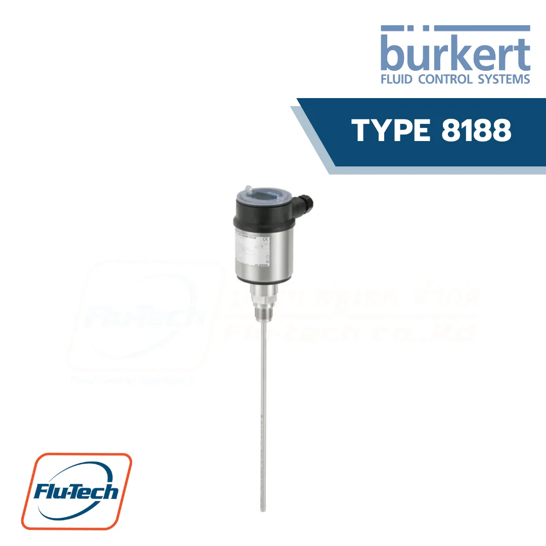
The Type 8188 is a level measurement device with cable, rod, both interchangeable probe or with coax probe, designed for continuous level measurement. The unit is suitable for liquids, for industrial use in all areas of process technology. With a measuring range up to 75 m, the 8188 is best suited for tall vessels. Even process conditions such as strong steam generation, density fluctuations or changes of the dielectric constant do not influence the accuracy of the measurement. Build-up or condensation on the probe or vessel wall do not influence the measuring result. A liquid interface measurement is also possible with the Type 8188, typically an oil/water interface.
Downloads
Data Sheet User ManualGeneral Technical Data
Product properties |
|
| Materials | Please make sure the device materials are compatible with the fluid you are using. Detailed information can be found in chapter “4.1. Chemical Resistance Chart – Bürkert resistApp” on page 7. |
| Non wetted parts | |
| Housing | Plastic PBT (Polyester), PPS and stainless steel 316L (1.4404) |
| Cover | PC transparent |
| Seal between housing and housing cover | EPDM |
| Cable gland | PA |
| Blind plug | PA |
| Ground terminal | Stainless steel 316L |
| Wetted parts | |
| Process seal | NBR with aramid fibers |
| Dimensions | Detailed information can be found in chapter “5. Dimensions” on page 8. |
| Weights | Depending on the device version. Detailed information can be found in chapter “2. Product versions” on page 5. |
| Probe length | Depending on the device version. Detailed information can be found in chapter “2. Product versions” on page 5. |
| Measuring variable | Level of liquids. For solids applications, please contact your local Bürkert Sales Center. |
| Measuring range | Detailed information can be found in chapter “6.1. Measuring range and blocking dis-tance diagram” on page 11. |
| Damping (63 % of the input value) | 0…999 s, adjustable |
| Step response time2.) | ≤ 3 s |
| Product accessories Display | LCD in full dot matrix. Detailed information can be found in chapter “8.4. Ordering chart accessories” on page 17 |
Performance data |
|
| Blocking distance | Detailed information can be found in chapter “6.1. Measuring range and blocking dis-tance diagram” on page 11. |
| Measurement deviation | According to DIN EN 60770‑1: ± 2 mm Detailed information can be found in chapter “6.2. Measurement deviation diagram” on page 12. |
| Measuring range resolution | 1 mm |
| Measuring cycle time2.) | < 500 ms |
| Temperature drift | • Digital output: ± 3 mm/10 K, max. 10 mm • Current output: < 0.03 %/10K relating to the 16 mA span or ≤ 0.3 % |
| Max. filling/emptying speed | 1 m/min |
| Non-repeatability | ≤ ± 1 mm (max.) |
| Vibration resistance | Depending on the device version. Detailed information can be found in chapter “2. Product versions” on page 5. |
| Shock resistance | Depending on the device version. Detailed information can be found in chapter “2. Product versions” on page 5. |
Electrical data |
|
| Operating voltage (Un) | • Without display/configuration module: – 9.6…35 V DC – 9.6…30 V DC (Ex ia instrument) • With display/configuration module: – 16…35 V DC – 16…30 V DC (Ex ia instrument) |
| Power Source (not supplied) | Limited power source according to UL/EN 60950-1 standards or limited energy circuit according to UL/EN 61010-1 §9.4 |
| Starting current | ≤ 3.6 mA; ≤ 10 mA for 5 ms after switching on |
| DC reverse polarity protection | Yes |
| Output signal | 4…20 mA/HART |
| Signal resolution | 0.3 µA |
| Range of the output signal | 3.8…20.5 mA/HART (default setting) |
| Load resistor | (Un – Umin.)/0.022 A |
| Fault signal | Current output: mA value unchanged, 20.5 mA, 22 mA or < 3.6 mA (adjustable) |
| Max. output current | 21.5 mA |
| Residual ripple (at DC) | • For 9.6 V < Un < 18 V: ≤ 0.7 Veff (16…400 Hz) • For 18 V < Un < 35 V: ≤ 1.0 Veff (16…400 Hz) |
| Voltage supply cable | • Cable diameter: 5…9 mm • Wire cross-section (spring-loaded terminals): – massive wire, stranded wire: 0.2…2.5 mm2 (AWG 24…14) – stranded wire with end sleeve: 0.2…1.5 mm2 (AWG 24…16) |
Medium data |
|
| Process temperature | Depending on the device version. Detailed information can be found in chapter “2. Product versions” on page 5. |
| Process pressure | Depending on the device version. Detailed information can be found in chapter “2. Product versions” on page 5. |
| Dielectric constant (min.) | Depending on the device version. Detailed information can be found in chapter “2. Product versions” on page 5. |
Process/Port connection & communication |
|
| Process connection | Thread G or NPT ‑ ¾”, 1″ |
| Electrical connection | Cable glands M20 x 1.5 |
Approvals and Certificates |
|
| Standards Degree of protection according to IEC/EN 60529 |
IP66/IP67 with cable plug mounted and tightened M20 x 1.5 |
| Overvoltage category according to IEC 61010-1 | Category III |
| Protection class according to IEC 61010-1 |
Class III |
| Directives | |
| CE directives | The applied standards, which verify conformity with the EU Directives, can be found on the EU Type Examination Certificate and/or the EU Declaration of conformity (if applicable) |
| NAMUR recommendations | NE21- Electromagnetic compatibility of equipment NE43 – Signal level for fault information from measuring transducers NE53 – Compatibility of field devices and display/adjustment components NE107 – Self-monitoring and diagnosis of field devices |
| Certificate | |
| Approvals | |
| ATEX/IECEx | EN IEC 60079‑0, EN 60079‑11, EN 60079‑26 Detailed information can be found in chapter “3.1. Certifications” on page 7. |
Environment and installation |
|
| Ambient temperature | Operation and storage: – 40…+ 80 °C (- 40…+ 176 °F) (with display/configuration module) |
| Temperature derating | Depending on the device version. Detailed information can be found in chapter “6.3. Temperature derating diagram” on page 14. |
| Relative air humidity | 20…85 %, without condensation |
| Height above sea level | Max. 2000 m (by default; max. 5000 m with connected overvoltage protection) |
| Pollution degree | Degree 4 (when used with fulfilled housing protection) |
*For selecting thecorrect product please refer to the technical data, images and notes for proper use according to the data sheet, or contact Flu-Tech directly.
สอบถามข้อมูลเพิ่มเติม ติดต่อเรา :
02-384-6060 (อัตโนมัติ) [email protected] บริษัท ฟลูเทค จำกัด Flu-tech @flutech.co.th
