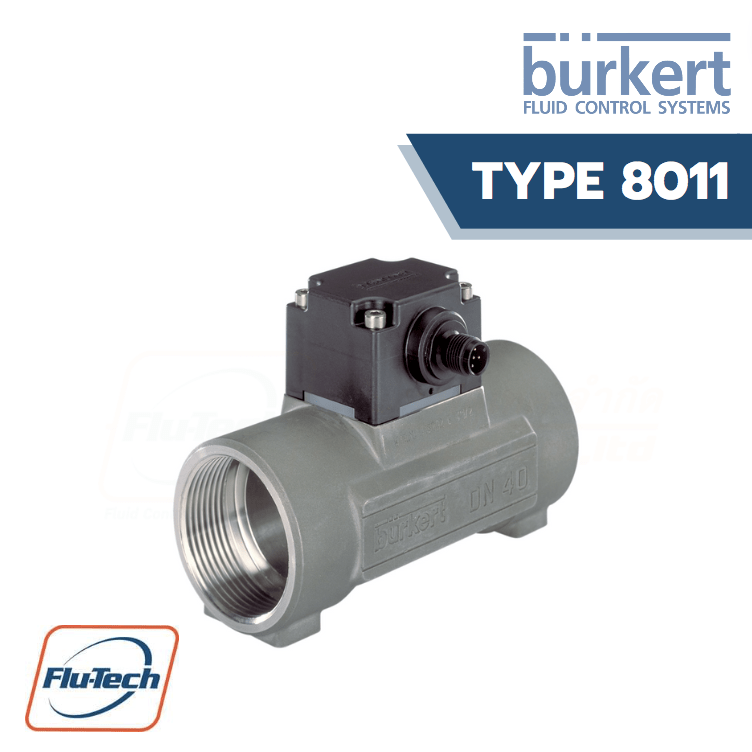
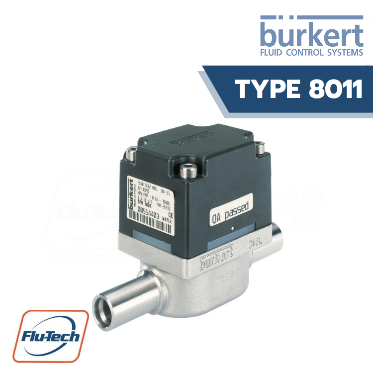
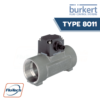
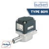
Inline Paddle Wheel Flow sensor for continuous flow measurement
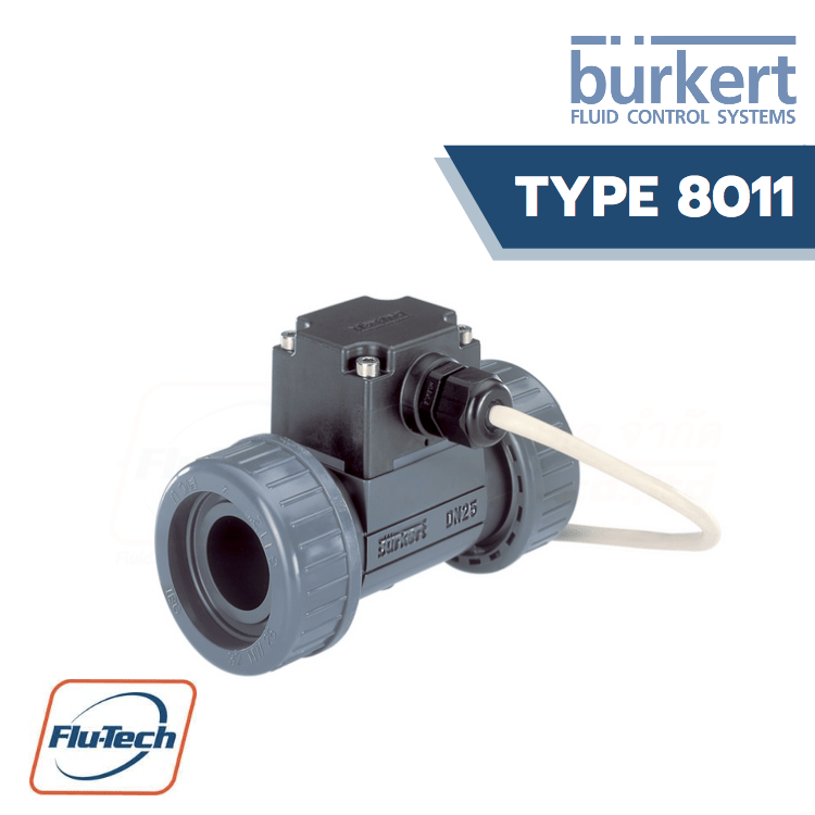
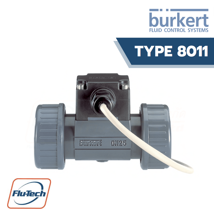
The Type 8011 paddle-wheel flow sensor for continuous flow measurement is especially designed for use in neutral, slightly aggressive, solid-free liquids. The sensor is made up of a fitting (S012) and an electronic module (SE11) connected together with screws. The Bürkert designed fitting system ensures simple installation of the sensor into all pipes from DN06 to DN65. It can also be installed in fluid block systems.The sensor produces a frequency pulse signal, proportional to the flow rate, which can easily be transmitted and processed by a Bürkert remote transmitter/indicator (type 8025/8032). The sensor is available in two versions:- with one pulse output: transistor NPN- with two pulse outputs: transistor NPN and PNP.
The type 8011 is not available anymore since 1/1/23.
Please contact us for a consultation regarding the most suitable successor article for your requirements.
DOWNLOAD CATALOG (ดาวน์โหลดแคตตาล็อก)
General Technical Data
Note: If the device is mounted in a humid environment or outside, then the maximum voltage allowed is 35 VDC instead of 36 VDC.
Product Properties |
|
|
Non wetted parts – Housing material
|
PPS
|
| Non wetted parts – Seal material | EPDM |
| Non wetted parts – M12 male fixed plug material | Stainless steel A4 |
| Non wetted parts – Cable gland with 1 m connected cable material (Availble on request) | PA |
| Wetted parts – Fitting material | PVC (cable) and PA (cable gland) |
| Wetted parts – Seal material |
Brass, stainless steel 1.4404/316L, PVC or PP FKM (EPDM option)
|
| Wetted parts – Axis and bearings material | Ceramics (Al2O3) |
| Wetted parts – Paddle wheel, holder material | PVDF (blue for paddle wheel) |
| Dimensions |
Detailed information can be found in chapter “4. Dimensions” on page 6.
|
|
Measuring element
|
Magnetic hall sensor |
| Compatibility |
Transmitter Type SE11 compatible with Bürkert fitting Type S012
|
| Pipe diameter |
DN 06…DN 50 (DN 65 on request)
|
| Measuring range | Flow rate: 0.5…1000 l/min (0.13…265 gpm) / Flow velocity: 0.3…10 m/s |
Performance Data |
|
|
Measurement deviation
|
Teach-In: ±1% of the measured value (at Teach-In flow rate value) / Standard K-factor: ±2.5% of the measured value
|
| Linearity |
±0.5% of full scale
|
| Repeatability |
±0.4% of the measured value
|
Electrical Data |
|
|
Operating voltage
|
One pulse output version: 4.5…24 V DC, filtered and regulated / Two pulse outputs version: 6…36 V DC, filtered and regulated / Connection to main supply: permanent (through external SELV (Safety Extra Low Volt- age) and LPS (Limited Power Source) power supply)
|
| Power Source (not supplied) |
Limited power source according to UL/EN 60950-1 standards or limited energy circuit according to UL/EN 61010-1 §9.4
|
| DC reverse polarity protection |
Yes
|
| Over-voltage protection | Yes |
| Current consumption | <5 mA (without load) |
| Outputs | One pulse output version: Transistor NPN, open collector / Two pulse outputs version: Transistor: NPN or PNP, open collector |
|
Voltage supply cable
|
Max. 1.5 mm2 cross-section
|
Medium Data |
|
|
Fluid temperature
|
With fitting in: • PVC: 0…+ 60 °C (+ 32…+ 140 °F) • PP: 0…+ 80 °C (+ 32…+ 176 °F) • Stainless steel or brass: – 15…+ 100 °C (+ 5…+ 212 °F) (if T°ambient ≤ + 45 °C) or -15…+90 °C (+5…+194 °F) (if +45 °C ≤ T°ambient ≤+60 °C) |
|
Fluid pressure
|
Max. PN 10 (145 PSI) with plastic fitting • Max. PN 16 (232 PSI) with metal fitting Detailed information can be found in chapter “5.1. Pressure temperature diagram” on page 8. |
|
Viscosity
|
Max. 300 cSt
|
| Rate of solid particles | Max. 1% |
| Maximum particle size | 0.5 mm |
Process/Port Connection & Communication |
|
|
Port connection
|
• Metal: Internal or external thread (weld ends, clamp or flange on request) • Plastic: True union with nut and solvent socket, external thread (spigot on request) |
| Electrical connection | 5 pin M12 male fixed plug or with 1 m cable via cable gland |
Approvals and Certificates |
|
| Standards – Degree of protection according to IEC/ EN 60529 |
IP67 with device wired and M12 cable plug mounted and tightened / IP65 with cable gland
|
| CE directives |
The applied standards, which verify conformity with the EU Directives, can be found on the EU Type Examination Certificate and/or the EU Declaration of conformity (if applicable)
|
| Pressure equipment directives |
Complying with Article 4, Paragraph 1 of 2014/68/EU directive
|
| Certificate | On request: • Inspection certificate 3.1 (acc. to EN-ISO 10204) • Test report 2.2 (acc. to EN-ISO 10204) • Certification of conformity for the surface quality DIN4762-DIN4768-ISO/4287/1 • 3 points flow calibration certificate |
Environment and Installation |
|
|
Ambient temperature
|
Operation and storage: – 15…+ 60 °C (+ 5…+ 140 °F)
|
| Relative air humidity | ≤80%, without condensation |
| Height above sea level |
Max. 2000 m
|
| Operating condition | Continuous |
| Equipment mobility | Fixed |
| Application range |
Indoor and outdoor (Protect the device against electromagnetic interference, ultraviolet rays and against the effects of climatic conditions)
|
| Installation category | Category I according to UL/EN 61010-1 |
| Pollution degree | Degree 2 according to UL/EN 61010-1 |
*For selecting the correct product please refer to the technical data, images and notes for proper use according to the data sheet, or contact Flu-Tech directly.
สอบถามข้อมูลเพิ่มเติม ติดต่อเรา :
02-384-6060 (อัตโนมัติ) [email protected] บริษัท ฟลูเทค จำกัด Flu-tech @flutech.co.th
