

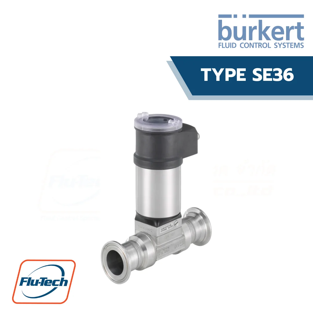
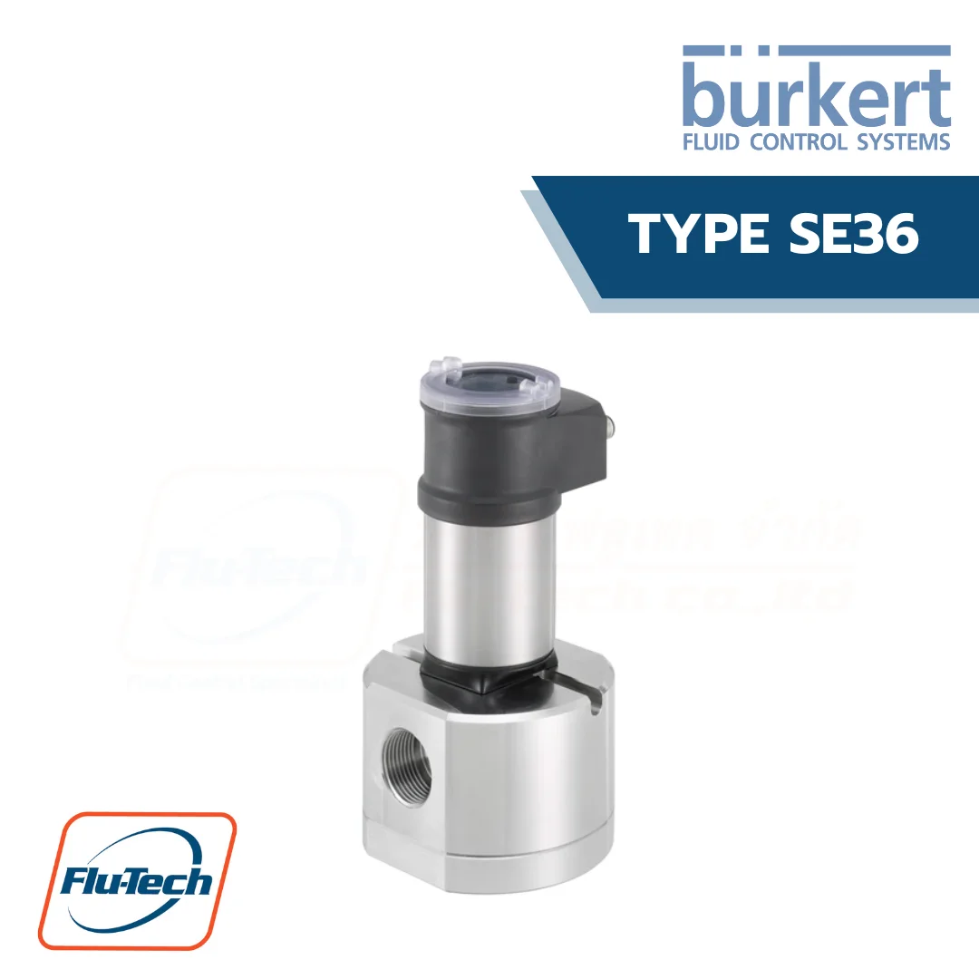


Positive displacement flowmeter, ELEMENT design
DOWNLOAD CATALOG (ดาวน์โหลดแคตตาล็อก)
TYPE se36 สามารถใช้ได้ร่วมกับ
-
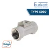 Burkert - Type S030 Inline Sensor Fitting with Paddle Wheel for Flow Measurement
-
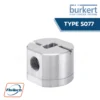 Burkert - Type S077 Positive Displacement Sensor Fitting for Continuous Flow Measurement
-
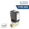 BURKERT - TYPE 6213 2/2 Way Servo-Assisted Diaphragm Valve
-
 Burkert - Type 8619 multiCELL Multi Channel and Multi Function Transmitter / Controller
-
 Burkert - Universal Process Controller Type 8611
-
 Burkert - Type 8644 AirLINE SP electropneumatic automation system
-
 BURKERT - TYPE 2030 Pneumatically operated 2/2 way diaphragm valve CLASSIC with plastic valve body
-
 BURKERT - TYPE 8692 Digital Electropneumatic Positioner for Integrated Mounting on Process Control Valves
General Technical Data
Product properties |
|
| Material | Please make sure the device materials are compatible with the fluid you are using. Detailed information can be found in chapter “3.1. Chemical Resistance Chart – Bürkert resistApp” on page 6. |
| Non wetted parts | |
| Housing | Stainless steel 1.4404 (316L), PPS |
| Cover | Polycarbonate (PC), transparent (opaque on request) |
| Display/configuration module | PC |
| Navigation key | PBT |
| Seals | EPDM, silicone |
| Screws | Stainless steel 1.4401 (316 (A4)) |
| Fixed connector holder | PPS CF30 |
| Fixed connector | Nickel-plated brass (stainless steel on request) |
| Grounding terminal and screw | Stainless steel 1.4301 (304 (A2)) |
| Quarter turn system | PC |
| Wetted parts | |
| Sensor-fitting body | Aluminium or stainless steel (316L) |
| Seal | FKM or FEP/PTFE encapsulated |
| Oval gear | PPS, aluminium or stainless steel (316L) |
| Shaft | Stainless steel (316L) |
| Product accessories Display/configuration module | Grey dot matrix 128 x 64 with backlighting |
Performance data |
|
| Measurement deviation | • With K-factor determined with a teach-in procedure or with the specific K-factor, engraved on the sensor-fitting: ± 0.5 % of the measured value (at Teach-In flow rate value) • With standard K-factor: ± 1 % of the measured value |
| Repeatability | ± 0.03 % of the measured value |
| 4…20 mA output uncertainty | ± 1 % of range |
Electrical data |
|
| Operating voltage | • 2 or 3 outputs transmitter (2-wire) version: 14…36 V DC, filtered and regulated • 4 outputs transmitter (3-wire) version: 12…36 V DC, filtered and regulated Connection to main supply: permanent (through external SELV (Safety Extra Low Volt-age) and LPS (Limited Power Source) power supply |
| Power source (not supplied) | Limited power source according to UL/EN 60950-1 standards or limited energy circuit according to UL/EN 61010-1 §9.4 |
| DC reverse polarity protection | Yes |
| Overvoltage protection | Yes |
| Current consumption | With sensor • ≤ 1 A (with transistors load) • 2 or 3 outputs transmitter (2-wire) version: ≤ 25 mA (at 14 V DC without transistors load, with current loop) • 4 outputs transmitter (3-wire) version: ≤ 5 mA (at 12 V DC without transistors load, without current loop) |
| Power consumption | Max. 40 W |
| Outputs Transistor |
Protected against overvoltage, polarity reversals and short circuit • 1 transistor output (transmitter 2-wire): – NPN, open collector – 1…36 V DC – Max. 700 mA • 2 transistor outputs (transmitter 2 or 3-wire): – Adjustable as sourcing or sinking (respectively both as PNP or NPN ), open collector – Max. 700 mA – 0.5 A max. per transistor if the 2 transistor outputs are wired – NPN-output: 1…36 V DC – PNP-output: Power supply |
| Current | 4…20 mA adjustable as sourcing or sinking (in the same mode as transistor): • 1 current output (transmitter 2-wire) Max. loop impedance: 1100 Ω at 36 V DC; 610 Ω at 24 V DC; 180 Ω at 14 V DC • 2 current outputs (transmitter 3-wire) Max. loop impedance: 1100 Ω at 36 V DC; 610 Ω at 24 V DC; 100 Ω at 12 V DC |
| Voltage supply cable | For the female M12 connector and/or the male M12 connector (not supplied, to order separately, see chapter “9.5. Ordering chart accessories” on page 11) use a shielded cable. • Ø 3…6.5 mm • Cross section of wires: max. 0.75 mm² |
Medium data |
|
| Fluid temperature | With sensor-fitting S070 in: • Aluminium: – 20…+ 80 °C (- 4…+ 176 °F) • Stainless steel: – 20…+ 120 °C (- 4…+ 248 °F) See data sheet Type S077 for more information. |
| Fluid pressure (max.) | • DN 15: 55 bar (798.05 PSI) (threaded process connection) • DN25: 55 bar (798.05 PSI)1.) • DN40 or DN50: 18 bar (261.18 PSI) • DN80: 12 bar (174.12 PSI) • DN100: 10 bar (145.1 PSI) See data sheet Type S077 for more information. |
| Viscosity | Max. 1 Pa.s (higher on request) |
| Rate of solid particles | 0% |
Process/Port connection & communication |
|
| Process connection | • Thread: ½”; 1″; 1½”; 2″; 3″ (G or NPT) • Flange: – 25; 40; 50; 80 or 100 mm DIN PN16 flange – 1″; 1½”; 2″; 3″ or 4″ ANSI 150LB flange |
| Electrical connection | • 2 or 3 outputs transmitter (2-wire) version: 1 x 5 pin M12 male fixed connector • 4 outputs transmitter (3-wire) version: 1 x 5 pin M12 male and 1 x 5 pin M12 female fixed connectors |
Approvals and Certificates |
|
| Standards Degree of protection2.) |
IP65, IP67 (according to IEC/EN 60529), NEMA 4X (according to NEMA250) with device wired and M12 cable plug mounted and tightened and cover fully screwed down |
| CE directives | The applied standards, which verify conformity with the EU Directives, can be found on the EU Type Examination Certificate and/or the EU Declaration of conformity (if applicable) |
| Pressure equipment directives | Complying with Article 4, Paragraph 1 of 2014/68/EU directive Detailed information on the pressure equipment directive can be found in chapter “2.2. Pressure Equipment Directive” on page 5. |
| Certification | UL-Recognized for US and Canada |
Environment and installation |
|
| Ambient temperature | Operation and storage: – 10…+ 60 °C (+ 14…+ 140 °F) |
| Relative air humidity | ≤ 85 %, without condensation |
| Height above sea level | Max. 2000 m |
| Operating condition | Continuous |
| Equipment mobility | Fixed |
| Application range | Indoor and outdoor (protect the device against electromagnetic interference, ultraviolet rays and against the effects of climatic conditions) |
| Installation category | Category I according to UL/EN 61010-1 |
| Pollution degree | Degree 2 according to UL/EN 61010-1 |
*For selecting thecorrect product please refer to the technical data, images and notes for proper use according to the data sheet, or contact Flu-Tech directly.
สอบถามข้อมูลเพิ่มเติม ติดต่อเรา :
02-384-6060 (อัตโนมัติ) [email protected] บริษัท ฟลูเทค จำกัด Flu-tech @flutech.co.th